Building the Collector
To find the best location for the collector, I used some simple paper-glued-to-cardboard tools for performing a solar site survey.
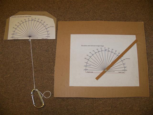
Gary Reysa has
a great page explaining how to do this, with links to the downloadable tools and graphs. Any obstacles that would produce shade at different times and different months of the year are plotted on a graph like this:
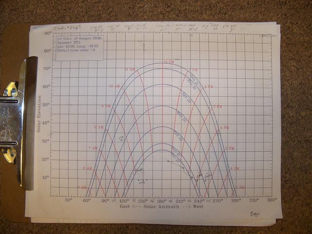
I found a spot in the backyard that should receive full sun for almost 6 hours in the winter, and longer in the summer. I designed the collector frame for a 60 degree tilt, to maximize gain in deep winter (we will have more heat than we need in the summer).
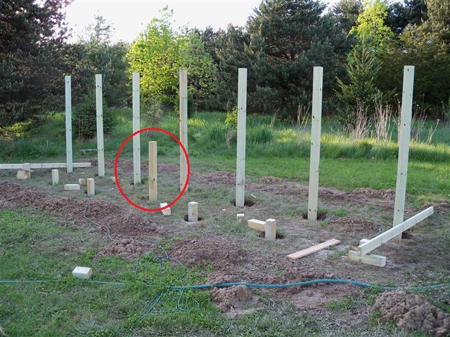
A farmer friend came out to drill fourteen 42" deep holes. Here my helper Chris Haggard and I are starting to position and brace the pressure treated 4x4s in the holes for the concrete that will be coming:

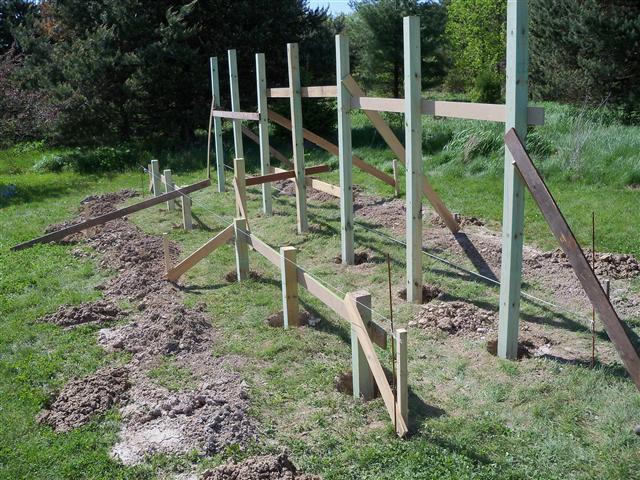
All braced:
We had a concrete truck come out and we used two wheelbarrows to run the concrete to the holes. They charged about $130, and it seemed worth it to avoid buying and hauling dozens of bags of dry mix. After the concrete had set, I used a skill saw to cut the tops off level:
Treated 2x4s made the span from the short posts in the front to the tall ones in back. The taller post in the middle front (next photo) was set back because the supply and return pipes would come into the panel from the back at the bottom center, and a normally-placed font post would have been in the way:
It rained twice between the time we had the post holes dug and the time we had completely filled in the holes. The first time, I had covered the holes with tarps, but becaue we are on a slope, the torrential rains flowed under the tarps and completely filled up many of the holes. I used a sump pump to empty them. After the concrete was poured, the 6 inches we left to be filled with dirt also filled with water.
Here Charles uses a siphon pump to pull the water out:

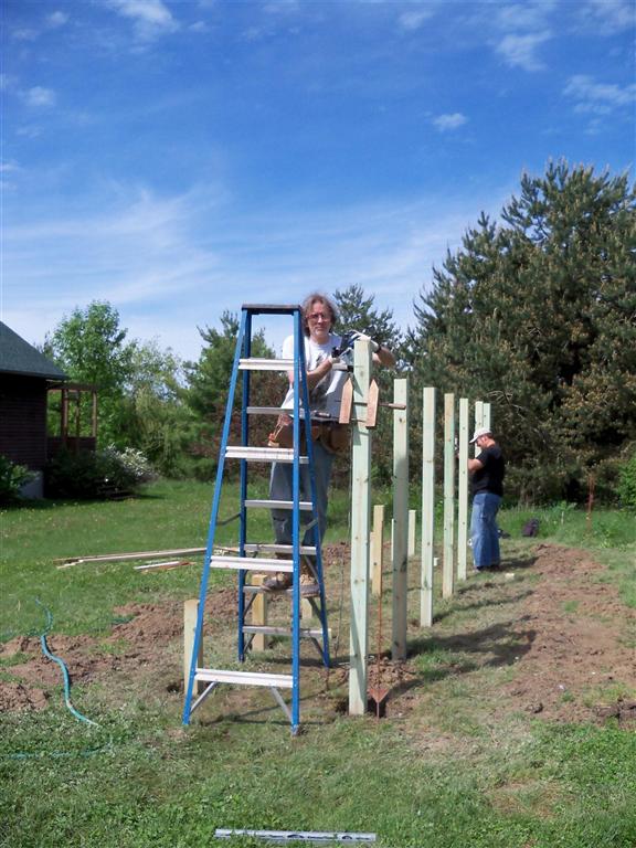
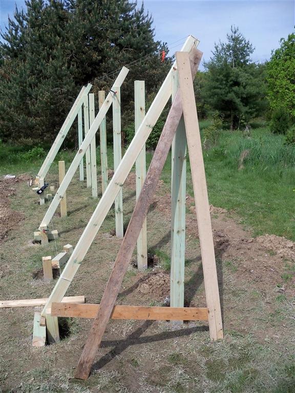
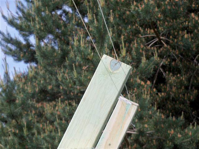
The 2x4 supports going up. Following Scott Davis' design, I used two 2x4s at each 4x4 post (to allow a surface to screw into through the plywood) — except at the last posts where a single 2x4 was used. By the way, I bought screws online from screw-products.com, and got their "Bronze Star" screws which they claim are safe for exterior use with treated wood. In front is a jig I used to help align the braces. We also ran lines to make things line up nicely:
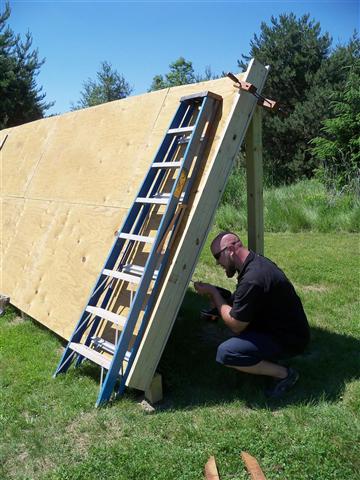
Next, 5/8" pressure treated plywood was screwed to the supports:
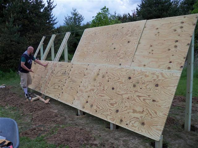
2x6 treated wood was used for the side and bottom edges to construct the overall collector frame:
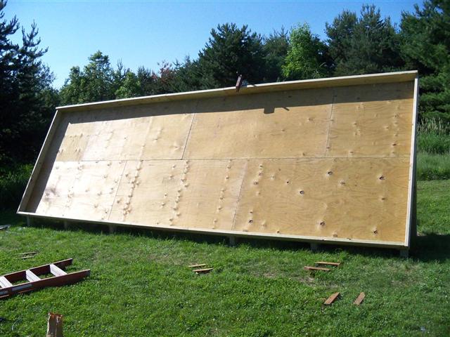
Amazing how quickly pressure treated wood — in this case plywood — will warp. But when the header was attached this bow straightened out:
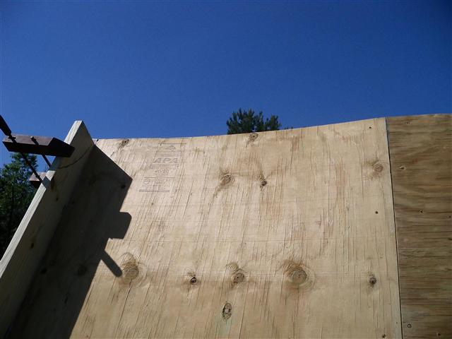
The header is treated 2x8, to provide more of an overhang. I thought this might help to keep driving rain out. The intention was to apply vinyl flashing to the top and bend it over at an angle to keep rain off the top of the glazing. (The claim is that aluminum flashing, even when painted, will corrode over time on treated lumber, hence the vinyl.) As of this writing, I have not yet put up the vinyl flashing, and I have not seen any water in the collectors even after a hard rain.
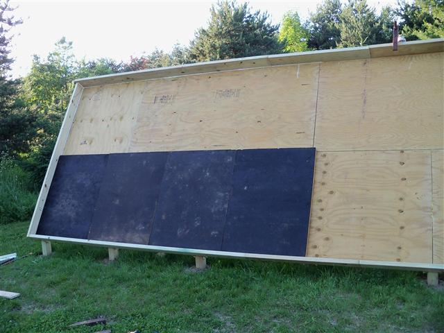
A friend had a huge load of 4 ft x 4 ft pieces of 1-1/2" thick polyisocyanurate foam, which handles heat much better than polystyrene, recycled from a commercial roof. This material can be found at most building supply stores under various trade names (including, I believe: Celotex GA3000 or Tuff-R, Kooltherm, Atlas R-Board, Thermax), but check to be sure. We simply laid these in on top of the backing plywood:
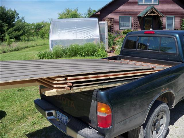
Here come the six collector panels, hauled from the university shop where we made them to our place (hoop greenhouse in the background):
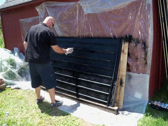
Chris painting the panels with black stove paint:
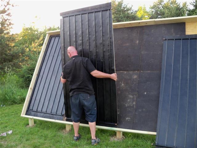
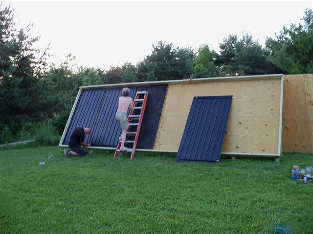
And setting them in the frame:
We taped the ends of the copper pipes to keep the paint off them, to make things easier for joining them:
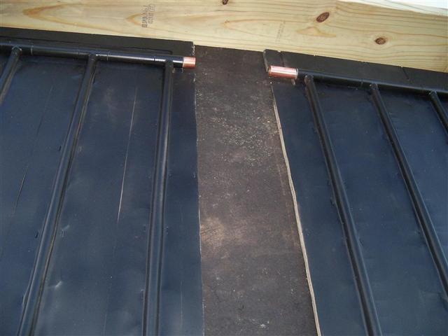
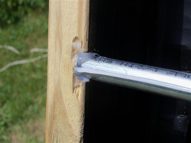
High-temp silicone automotive heater hose (7/8" ID) was used to join the pipe ends from panel to panel. I used 2" pieces, soaped them so they would slide more easily, and pushed the hose onto one pipe end all the way.
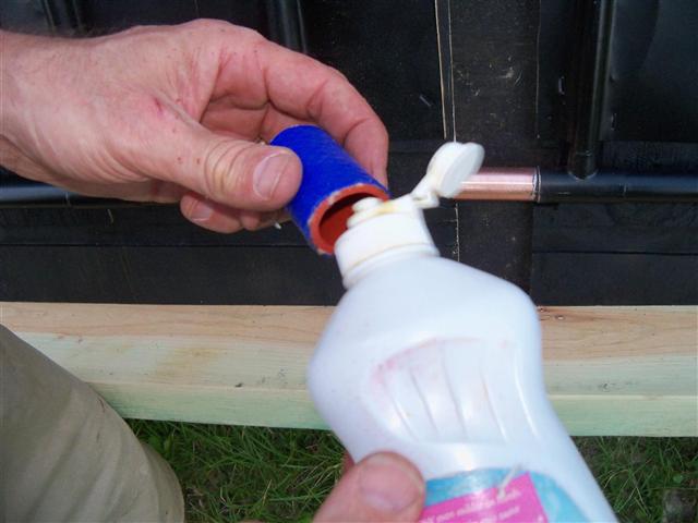
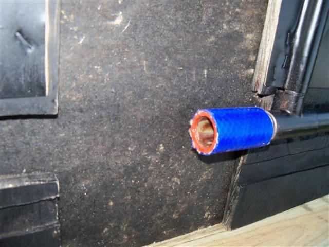
Then, when the panel was slid up to its neighbor, we slid the hose so that it bridged the small gap that was designed between the two copper stubs:
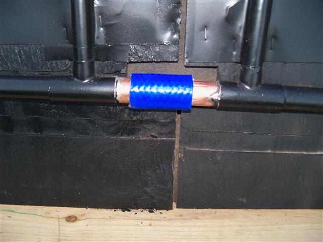
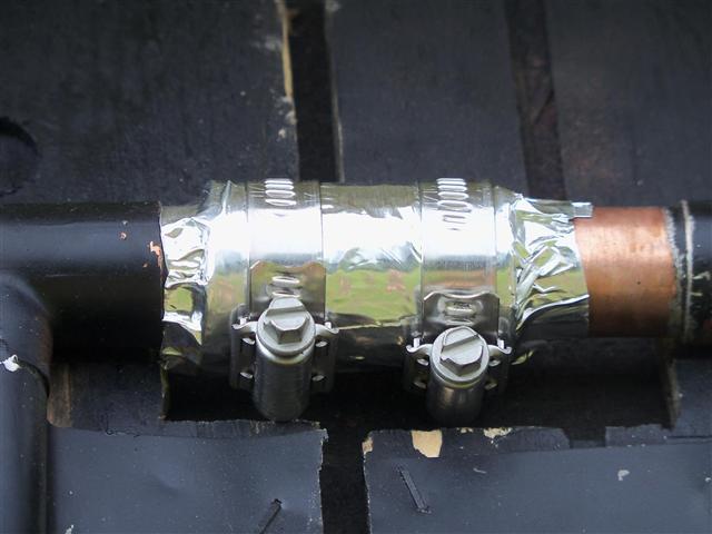
Two special stainless hose clamps were applied, of the kind that does not have cuts in the band but just indentations (so as not to cut into the hose). And the whole thing was wrapped with aluminum tape, as some say that the sun (unlike heat) will degrade the silicone:
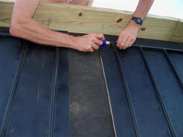
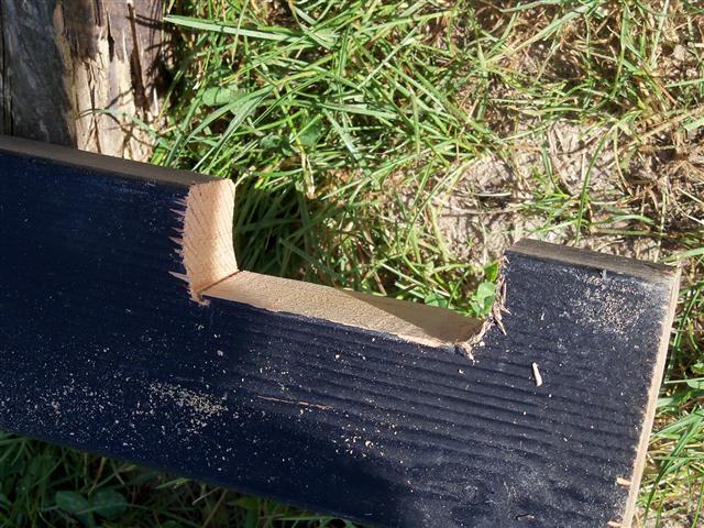
Once all panels were connected, I added vertical 2x4 dividers to separate each bay of the collector. This was needed to give a support for the 4x8 glazing panels. I had to notch the 2x4's to go over the pipe connectors top and bottom:
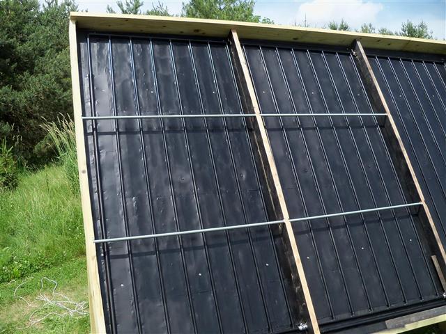
Here's a view of some panels with the 2x4 dividers installed. It worked out just right that the width of the 2x4 divider plus the array panel thickness plus the insulation made the 2x4 dividers flush with the outer 2x6's on the collector frame — which allowed the glazing to lie on the outer frame and on the dividers. (3.5"[2x4] + .5"[panel] + 1.5"[insulation] = 5.5"[2x6].) At the top, I will later add 2x4 pieces below the 2x8 header for the glazing to rest on. In the photo below I am adding the conduit across the dividers that will support the polycarbonate glazing against the wind.
Following Gary Reysa again, I laid a bead of silicone caulk on each conduit piece to be a cushion for the glazing, and let that dry lying flat for a day or two before messing with the conduit (so it would not drip with gravity.) I secured the conduit ends with caulk — in little routed grooves cut into the vertical supports:
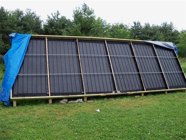
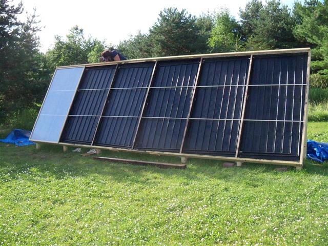
Here we have all panels assembled, with tarps ready to keep the rain out as we waited to apply the glazing. (Later I did not worry about a little rain when I had the glazing off for adjustments and diagnostics — as it runs out and the whole thing seems to dry out easily.) You can see the slope of the copper arrays towards the center.
To secure the 4x8 arrays to the collector frame, I added pieces of treated 2x4 between the supports at the back. Screwing from the arrays into the 5/8" backing plywood would not have been strong enough. The 2x4s gave the longer screws much better purchase, and the whole thing is tied together very strongly.
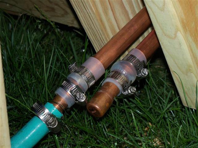
I did a pressure test on the assembled collector, hooking up the same stuff I used to test individual arrays. Here I am connected to the supply and return pipes at the back of the collector:
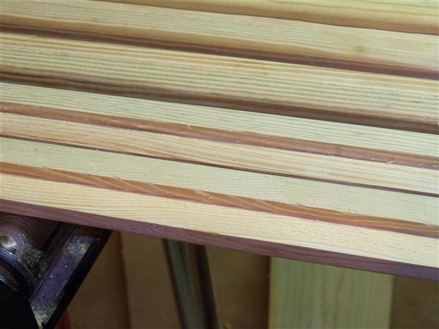
I bought 1-1/2" x 7/8" rounded treated trim pieces at Menards — which were cheap and perfect for my application — to use as the batten strips to secure the glazing to the frame. They had straight-grain pieces, which held their form very well.
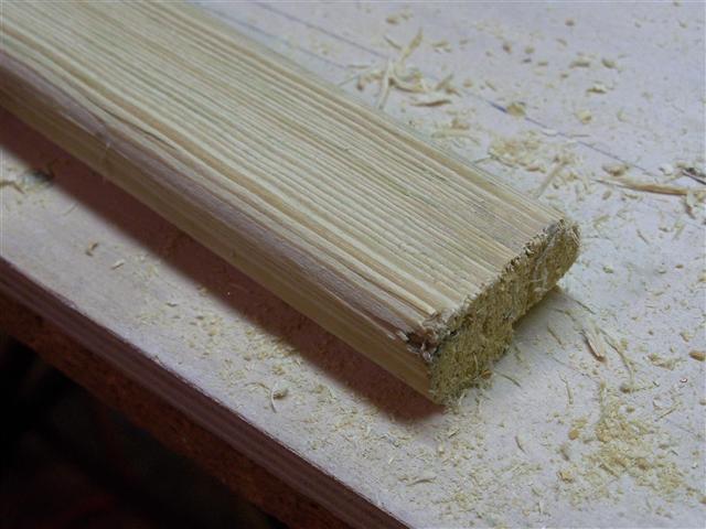
I made a little router jig to push the pieces through to make rabbets:
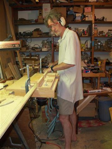
Some of the rabbetted pieces:
The next photo is the 2x8 header. These pieces were flush when they were added — and in a few days things had moved enough to open this gap. I caulked it and it seems that no more movement occurred after that, luckily.
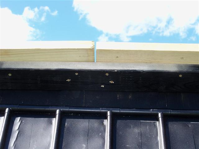
Also above you see the 2x4 that was added below the header, to act as a support for the glazing.
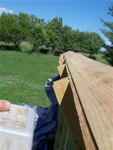
Looking along the edge of the header, you can see how the lumber has wiggled as it dried in the sun. Again, it seems to have stabilized over time:
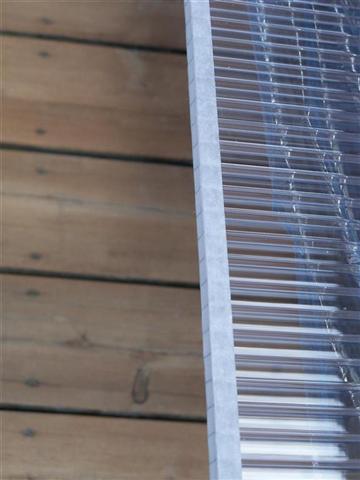
The twinwall polycarbonate glazing (4x8 sheets of 8mm thickness) was cut to size for each bay. (It would have been nicer if I had made it so that dimensions of each bay were exactly the same, but for various reasons I did not.) Each sheet was taped at the top with aluminum tape to disallow water from getting into the channels:
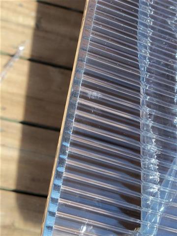
(The protective plastic sheet is still on, pulled back in the photo above). And at the bottom we applied a fabric tape that allows any condensation to drip out but no bugs to crawl in:
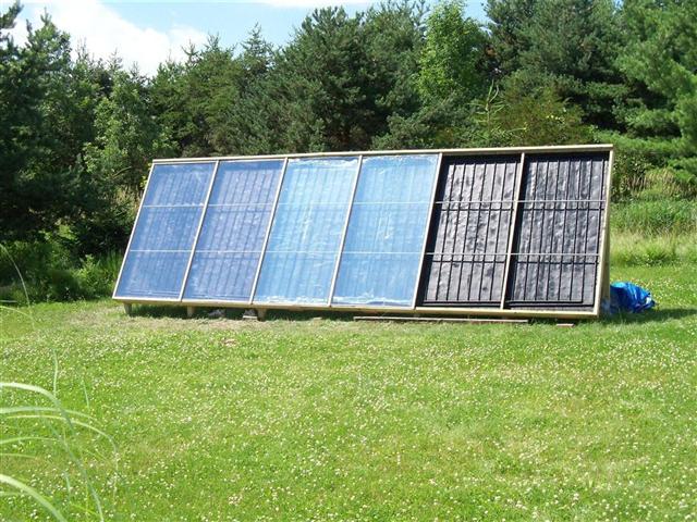
The first glazing panels go up:
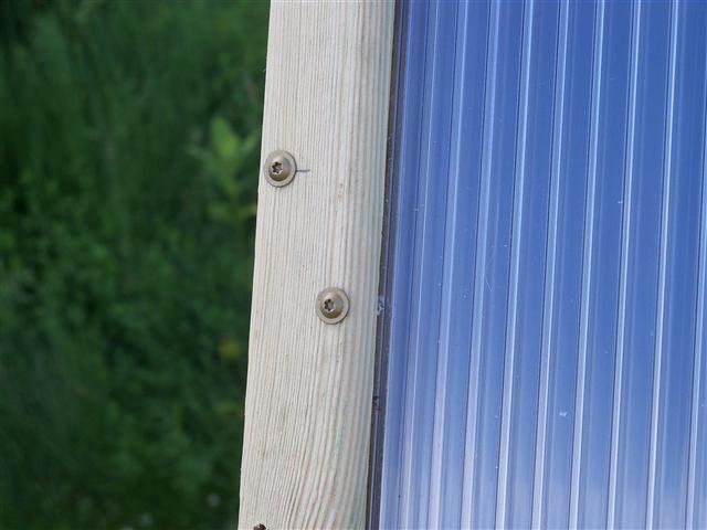
Here is an example of the treated trim boards that secure the glazing. No caulk or weather stripping is used. I cut a little slot in the edges of each glazing panel, in the middle, which rides over a screw (the inner screw in this photo). In theory this allows for expansion and contraction of the panels both vertically and horizontally. The screws hold the glazing up vertically in those slots — suspended so that the glazing can expand and contract vertically, with gaps left at top and bottom as needed. That is, the glazing does not sit all the way down in its rabbetted groove in the bottom trim piece, but is suspended.
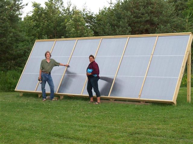
All the glazing up, my student intern Sherry and I real pleased:
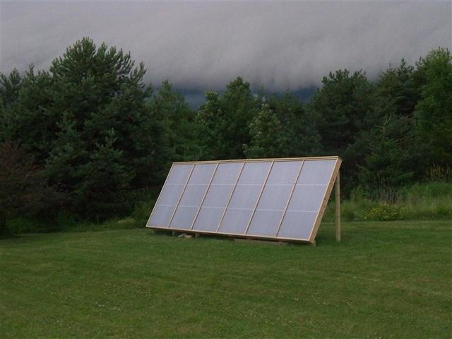
And a storm rolls in... A nice-looking wood-trimmed solar sculpture!
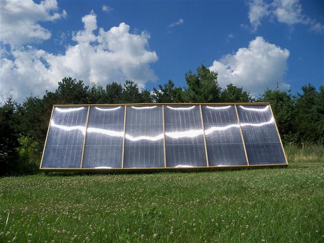
On a sunnier day:
 Next page (Tank and Heat Exchangers) >>